Friday, January 2, 2026

Q-emuLator 4.0 for Windows

Version 4.0 of Q-emuLator has been released for Windows 7 SP1 and later.


Extensive research went into making the CPU emulation cycle-accurate (also simulating its interaction with the ZX8301 video ULA and the 8049 coprocessor), creating a new lower-level format for microdrive images and studying the hardware of the ICL One Per Desk computer (a cousin of the QL).

Q-emuLator 4 also adds emulation of the QSound interface (3 sound channels), can run the pre-existing extended graphics modes inside a window, includes an improved ram disk driver and has more extensive debugging capabilities

For the nostalgic, there are monochrome monitor colour options and simulation of the microdrive motor and tape noise.

The overall experience of running the emulator should be smoother, with new features like default directories for ROMs/software/configurations, reduced audio latency, a Pause command (Windows-Alt-P), auto CPU speed setting, ability to create new empty MDV, MDVRAW, QXL.WIN and IMG file containers.

The manual has been updated and expanded and there are now an online troubleshooting page and a 'check for updates' command.

For a more detailed list of everything that's new in version 4, see this web page.

Sunday, January 8, 2023

Q-emuLator 2.2 for macOS

Q-emuLator for macOS version 2.2 has been released, now allowing the creation of subdirectories in QXL.WIN containers and on floppy disks. The included Toolkit 2 has been updated to a recent version that includes the SuperBASIC MAKE_DIR command.

Sunday, September 25, 2022

Q-emuLator 3.5 for Windows

The latest update of Q-emuLator for Windows implements the extended system call to create a new directory in a QXL.WIN container or floppy disk (in addition to a Windows directory, where it was already available). It's also bundled with a more recent version 2.34 of the Toolkit 2 that includes the MAKE_DIR command.

The built-in debugger (accessed by pressing F11 while the emulated QL is running) has been updated and it now supports conditional breakpoints, complex expressions and text that is more readable on large displays.

Friday, December 24, 2021

Q-emuLator updates

Q-emuLator versions 2.1 for OS X and 3.4 for Windows are now available for download.

SMSQ/e support has been improved when using the emulator-specific build of SMSQ/e (available here).

Both formats of microdrive images (mdump_task and QLay) are now supported by the unregistered version of the emulator, since supporting only one of them was confusing.

The version for Intel Macs also catches up with the TCP/IP driver improvements recently added to the PC version, and audio emulation has been made compatible with OS X 11 Big Sur.


Monday, September 7, 2020

Q-emuLator 2.0 for macOS

Q-emuLator 2.0 has been released, for Intel Macs running macOS 10.14 "Mojave" or later.


Apart from recompiling the code for 64 bit (32 bit apps are no longer supported since macOS Catalina), there has been extensive work to update functionality that relied on OS X APIs that Apple has discontinued or modified with incompatible behaviour.

Other changes are related to adjusting to the evolving macOS security constraints and to including some of the recent emulator changes that have been released in the Windows version. A few of these changes have also been applied to the 32 bit app (version 1.3.1) to make them available on older versions of OS X.

There is a new Quick Start Guide to help users new to Q-emuLator, or even the QL:


If you purchased a registration for version 1.x, this is a paid upgrade, except for people that have registered in the last year. (If you've registered in September 2019 or later, you may find that the new version already accepts your existing code, or contact me if it doesn't).

Sunday, May 10, 2020

Dumping Intel 8049 ROMs

In addition to the Motorola 68008, the QL has a second processor, named by Sinclair the "Intelligent Peripheral Controller" (IPC).

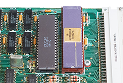
The second processor is an Intel 8049 microcontroller that runs independently of the main processor and handles the keyboard, sound and serial port inputs.

The 8049 sits on the right side of the QL motherboard, squeezed between the microdrives and the keyboard connectors

Communication between the 60008 and IPC uses a slow serial link and can only happen when the IPC is in-between activities like scanning the keyboard or producing the next segment of a sound.

This can cause a significant slowdown of QL software and the exact timing depends on the code that runs on the IPC.

The code is stored in an internal 2 KB ROM. Sinclair wrote the code, but it got programmed in the chip by the manufacturer, and there is no way to reprogram it.
This also means that if you need to replace an IPC chip, you cannot just buy any available 8049: It needs to come from a QL, or it will contain a different, incompatible ROM.

There are a few copies of the QL IPC code on the internet and they are all the same, apart for a single unused byte toward the end of the ROM.

In order to improve the 'QL Speed' accuracy of Q-emuLator, I plan to better account for the 8049 timings (simulating the interaction between the 68008 andthe ZX8301 ULA will also be necessary, but that's a topic for another day). To compare the speed measured on a real QL to the emulation speed, I need to be sure about what code is running on the IPC, so I decided to dump the contents of the chip and compare them to the version from the internet.

EPROM programmers have the circuitry necessary to read the 8049 ROM, but I don't know of any programmers that support this chip, probably because it cannot be written to.
Reading the ROM can be accomplished by using the "ROM Verification Algorithm" described in the MCS-48 datasheet (MCS-48 is the family of microcontrollers that includes the 8049).

I bought an Arduino UNO board to connect it to the 8049 and read the ROM.

I also got a second QL 8049 to use in my initial experiments and avoid the risk of ruining the chip in my QL.

My two IPC chips look quite different... Will they contain the same or different code?

There is a web page called 8049 Spy that explains how to connect the 8049 for reading the ROM.

I used the same method, with two differences:
  • The 8049 is connected to an Arduino instead of the 6802 Nano Computer.
  • I added a resistor for protection on each of the 8 data lines since these are bidirectional and both the Arduino and 8049 could end up trying to write to them at the same time if the timings are not perfect.

The IPC (on the right) connected to the Arduino board (left)

View from above
Here is the procedure to read the contents of the 8049 ROM:
  1. Apply 12 Volt to pin 7 to set the "ROM Verification" mode. In my circuit, I used a boost converter to convert the +5V used by the 8049 and Arduino to +12V.
  2. Set the 11-bit address of the ROM location to read, using DB0-DB7 for the low 8 bits and P20-P22 for the high 3 bits.
  3. Set the RESET pin to high to signal that the address is valid.
  4. After a few cycles, read the content of the ROM location from DB0-DB7.
  5. Set RESET to low and repeat from step 2 using the next address, until we've read all the 2048 ROM locations.
The Arduino code prints each ROM byte in hexadecimal to the serial link where the PC can read it (through the USB port) and display it (the Arduino IDE has a Serial Monitor window for that purpose).

Here are the connections from each of the 40 pins of the 8049 to the Arduino and other signals:

8049 connections for ROM Verification
The 11 bits for the address/data lines are connected to digital pins D2-D12 of the Arduino, while pin A0 (used as a digital pin) controls the 8049 RESET signal.

In addition to the resistors and boost converter, the only components needed are a 4 MHz crystal and two 22 pF capacitors to generate the clock signal.

Here is the code I wrote on the Arduino to read the ROM:
  #define RESET_PIN A0  
   
  void SetReset(uint8_t b) {
      digitalWrite(RESET_PIN, b);  
  }  
   
  void SetDigitalPinDir(bool bOut) {
     if (bOut) {  
         DDRD = B11111100 | DDRD;  
         DDRB = B00011111;  
     } else {  
         DDRD = B00000011 & DDRD;  
         DDRB = 0;  
     }  
  }  
   
  void SetAddress(int addr) {
      PORTD = ((uint8_t)addr << 2) | (PORTD & 3);  
      PORTB = (uint8_t)(addr >> 6);  
  }  
   
  uint8_t ReadDataBus() {  
      return (PIND >> 2) | (PINB << 6);  
  }  
   
  void Output(uint8_t b) {
      if (b < 16)  
          Serial.print("0");  
      Serial.print(b, HEX);  
  }  
   
  void OutputNewLine() {
      Serial.println();  
  }  
   
  int addr;  
   
  // Diagnostics  
  uint8_t diff;  
   
  void setup() {  
      SetDigitalPinDir(false);  
      pinMode(RESET_PIN, OUTPUT);  
      SetReset(LOW);  
      addr = 0;  
      diff = 0;  
   
      Serial.begin(9600);  
      while (!Serial); // Wait until serial console is opened  
  }  
   
  void loop() {  
   
      if (addr < 2048) {
 
          SetDigitalPinDir(true);  
          SetAddress(addr);  
          delayMicroseconds(100);  
          SetReset(HIGH);  
   
          delayMicroseconds(5);  
   
          SetDigitalPinDir(false);  
          SetAddress(255); // Input pullups  
          delayMicroseconds(2);  
   
          uint8_t data = ReadDataBus();  
   
          SetReset(LOW);  
          delayMicroseconds(10);  
     
          Output(data);  
   
          diff |= (data ^ addr);  
   
          addr++;  
   
          if ((addr & 31) == 0) {
              OutputNewLine();  

              if (addr == 2048) {
                  pinMode(RESET_PIN, INPUT);  
       
                  diff ^= 255;  
                  if (diff) {  
                      Serial.print("Some data lines appear disconnected: 0x");  
                      Output(diff);  
                      OutputNewLine();  
                  }  
              }  
          }  
      }  
  }     

Tweaking the code to make it work took longer than I expected. I found that initially some pins of the 8049 were not making good contact with the breadboard. After straightening the pins and reinserting the 8049, I started getting some data that looked correct, but other bytes or bits were read as zeros. Setting the Arduino digital pins in a input pullup configuration helped, but there were still some remaining zeros. I continued to look for bad contacts, but in the end it turned to be a timing issue and adding or increasing the timeouts in the code finally resulted in a good ROM dump.

I found that both the 8049s I dumped contained identical code. The code also matched the one already available online. This was less exciting than discovering a new version of the IPC ROM, but at least now I'm sure about what is running on my QL (JM version) and know that any small remaining speed differences in the emulator must be caused by something else.

It would be interesting to dump the IPC ROM of an early QL and see whether the code is also the same.

Sunday, November 5, 2017

Q-emuLator 3.2 for Windows


An update of Q-emuLator for Windows is now available at http://www.terdina.net/ql/winql.html.

New features:

  • Support for “mdump version 2” microdrive images
  • Use the original Sinclair device driver to access microdrive images
  • mdump_task now included in the FileUtil directory; Use it on a QL to create images of your microdrive cartridges (also works with any copy-protected software you own) that can be used with the emulator
  • Accurate sound timbre
  • Save QL screen snapshots to the desktop by pressing CTRL+F11

This version also includes many small compatibility improvements.

The payment processing service for registration has changed to Paypal.


Using the Sinclair device driver for microdrive access

Here is the new option to use the QDOS driver to access microdrive images (only works when using Sinclair ROMs):

LowLevelMdv

The option is enabled by default. The tradeoff is that access to microdrive images becomes much slower compared to the Q-emuLator device driver (used when the option is not checked). The simulated tape speed is about twice that of a real QL, so loading programs may take a few seconds.

Note that this option only applies to microdrive images; Other media attached to virtual microdrive slots still use the Q-emuLator device driver, as those types of media are not supported by the original QL ROM.

A few early software titles for the QL used copy protection schemes where they accessed the microdrives through QDOS calls, but then did some extra checks at fixed memory addresses where the Sinclair driver would store some of its internal data or cached sectors. There is even software that reads extra sectors from the tape after turning the motor off, relying on the inertia of the motor.

All of these more exotic protection schemes now work correctly in Q-emuLator when using a microdrive image containing a dump of the original copy-protected cartridge and using Sinclair ROMs with the “QDOS MDV image driver” option enabled.